NAR L1 Rocket

High-powered rocket and chute with H-impulse motor

NAR L1 Rocket

Summary

I designed, built, and launched a high-powered rocket under the guidance of the Tufts SEDS Rocketry Club as part of a National Association of Rocketry (NAR) Level 1 certification attempt. My primary goal was to maximize apogee using a low-impulse H-class motor by minimizing mass while maintaining a conservative stability margin. I designed and simulated the rocket in OpenRocket and modeled key components in Onshape. The rocket achieved a successful ascent and parachute deployment during its November 2024 launch.

Key Features

Lightweight airframe with 60 cm body tube Laser-cut plywood fins reinforced by three centering rings 3D-printed nose cone with integrated shock-cord Jolly Logic chute release for altitude-based deployment

Design Constraints

  • Flight stability must exceed 1.6 calibers
  • Rocket must have an intact recovery
  • Mass must be minimized

Flight Optimization

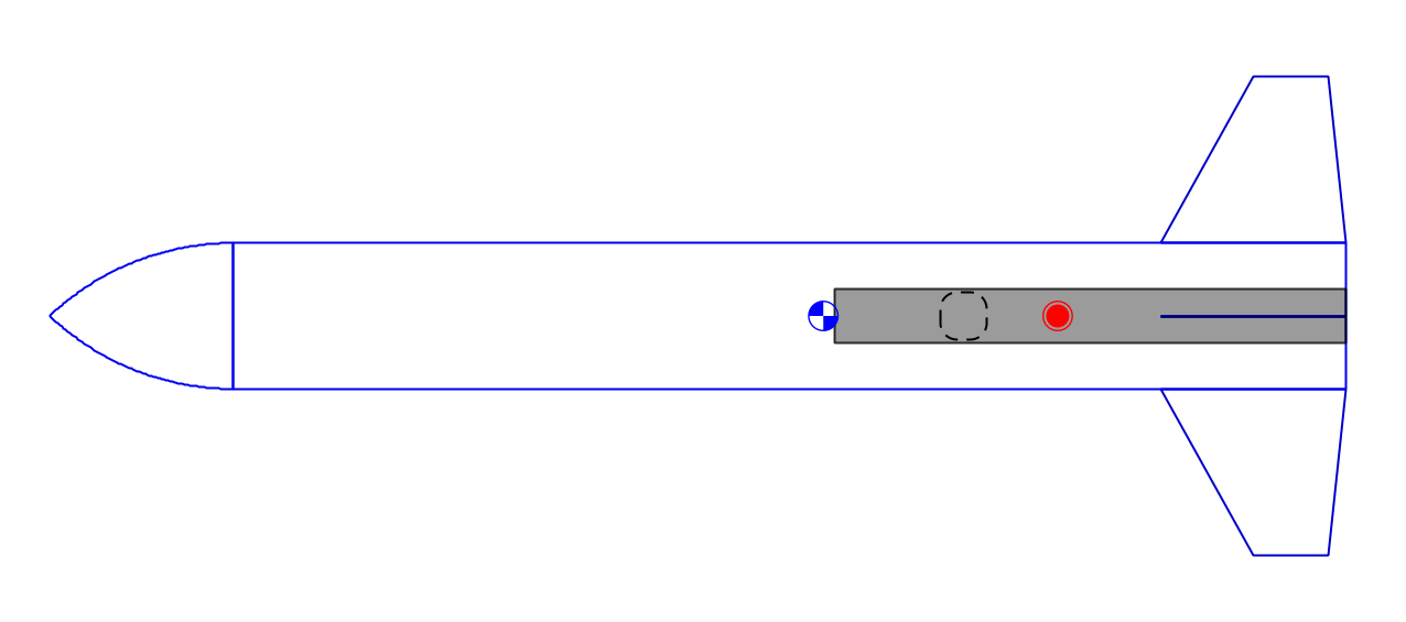
I used OpenRocket to simulate the effects of body tube length, motor impulse, fin geometry, and nose cone shape on apogee and stability. While higher-impulse motors and longer body tubes increased altitude, their combination reduced stability. To balance these trade-offs, I selected the lowest available H-impulse motor and minimized body tube length while maintaining a conservative stability margin.

The final design used a 60 cm body tube with a stability margin of 1.61 calibers on an H140 motor. The simulated mass was 1.03 kg, with a predicted apogee of 611 m, making it one of the lightest L1 rockets the team has built.

Flight Optimization
Fin Assembly

Fin Assembly

I imported the fin profile from OpenRocket into Onshape and laser-cut the fins and centering rings from 1/16 in birch plywood. I designed the fin system to accommodate different loads. The top centering ring carried parachute-deployment loads, while the bottom ring transferred motor thrust. I reinforced those rings by assembling them with two pieces of plywood.

The middle centering ring was positioned below the fin root chord to support exposed fin sections. I slotted the fins through the centering rings and epoxied the assembly into a rigid, integrated fin can before installing it into the body tube.

Systems Integration

I designed a 3D-printed nose cone in Onshape with a snug body-tube fit and an internal channel for shock-cord routing. The nose cone, parachute release, and fin assembly were connected via a continuous shock cord to ensure all components remained tethered during flight. I installed the fin can by cutting through-wall slots in the body tube and epoxying the assembly in place, creating a strong mechanical interface between the airframe and fins.

Rocket Assembly