Summary
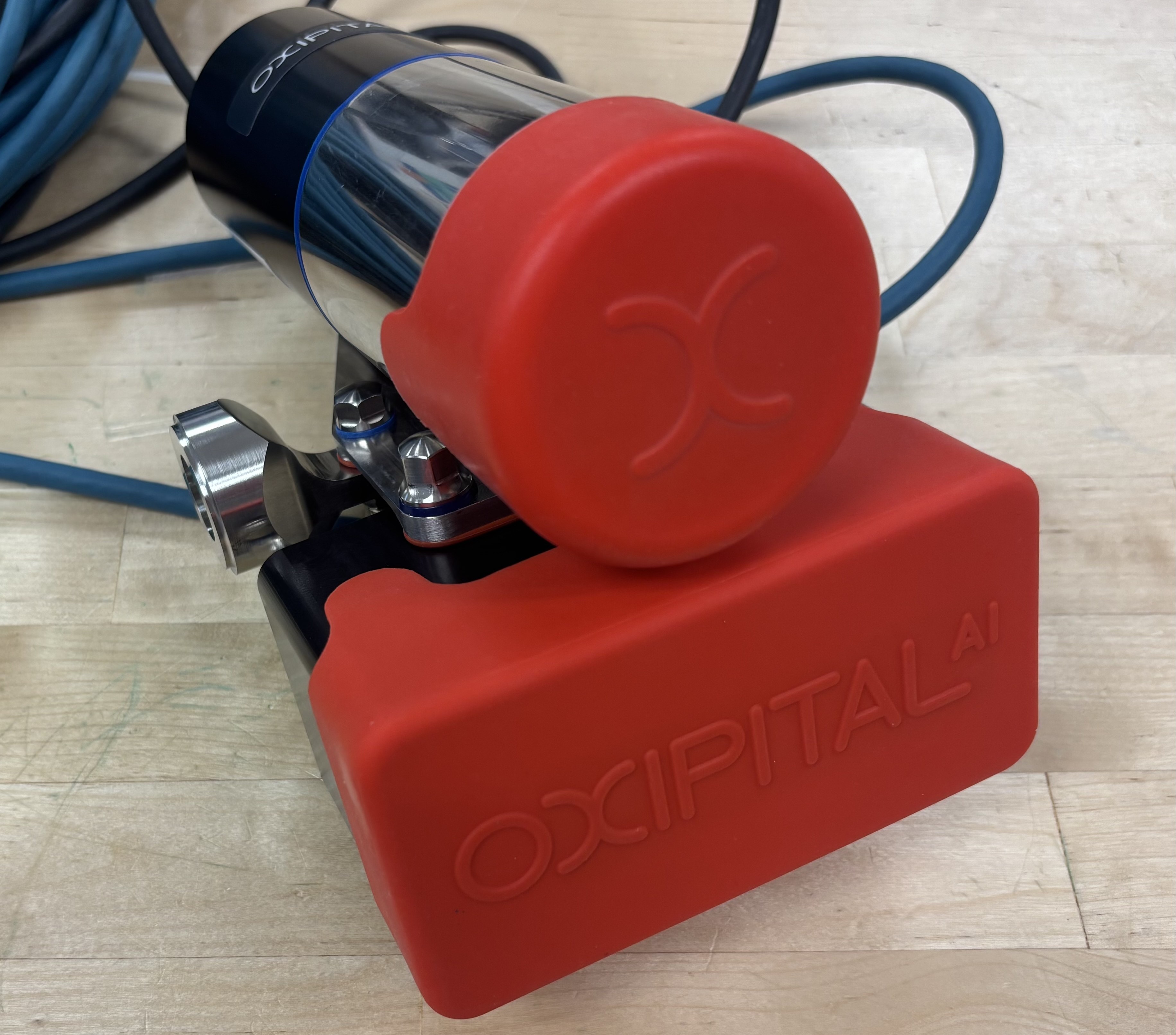
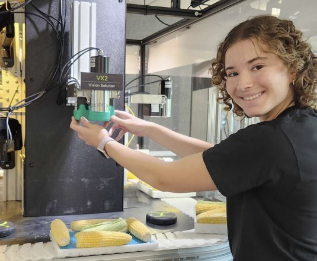
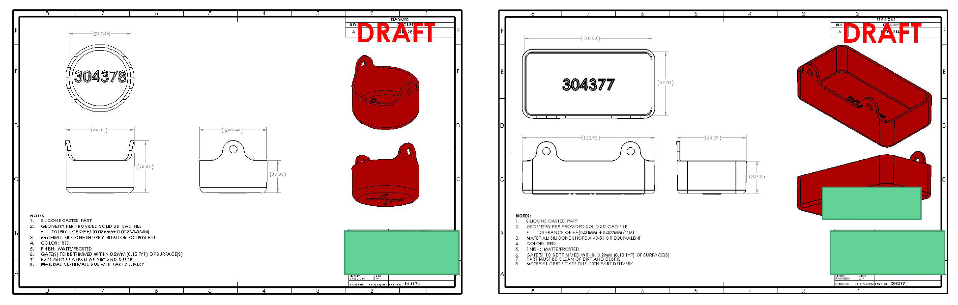
I designed and sourced manufacturing for two reusable camera lens caps to protect an industrial vision system during shipping and cleaning in food-safe environments. The caps were designed to form a friction fit with the camera body while remaining easy to install and remove. I went through several design iterations, prototyping the caps by hand with molded silicone to evaluate fit and tolerance sensitivity.
The final design used vertical pull tabs to improve removability while maintaining compatibility with existing packaging. The design was approved through internal design reviews and released for internal use.
Key Features
Silicone elastomer material for a compliant fit Short walls with pull tabs enabling one-handed removal Slim profile designed to shed water during cleaning
Functionality
- Lens cap must withstand cleaning with pressurized water
- Operator must be able remove the lens cap with one hand
- Existing packaging must fit cameras with the lens caps
Manufacturability
- Material must be compatible with food safe environments
- Lens cap must be bright colored for operator to see
- Parts must be manufactured in batches of 25
Early Design Decisions
Material: Silicone Elastomer
I selected a silicone elastomer with a Shore 40A hardness for the lens caps, balancing water resistance with flexibility for easy one-handed removal. The compliant material provides a reliable friction fit, resists pressurized water, and meets food-safe requirements.
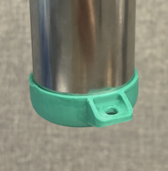
Removal Mechanism: Pull Tab
I designed the lens cap with a pull-tab feature, allowing an operator to remove the cap with one hand without sacrificing secure retention during washdowns. The tab also provides a simple way to tether multiple caps together.
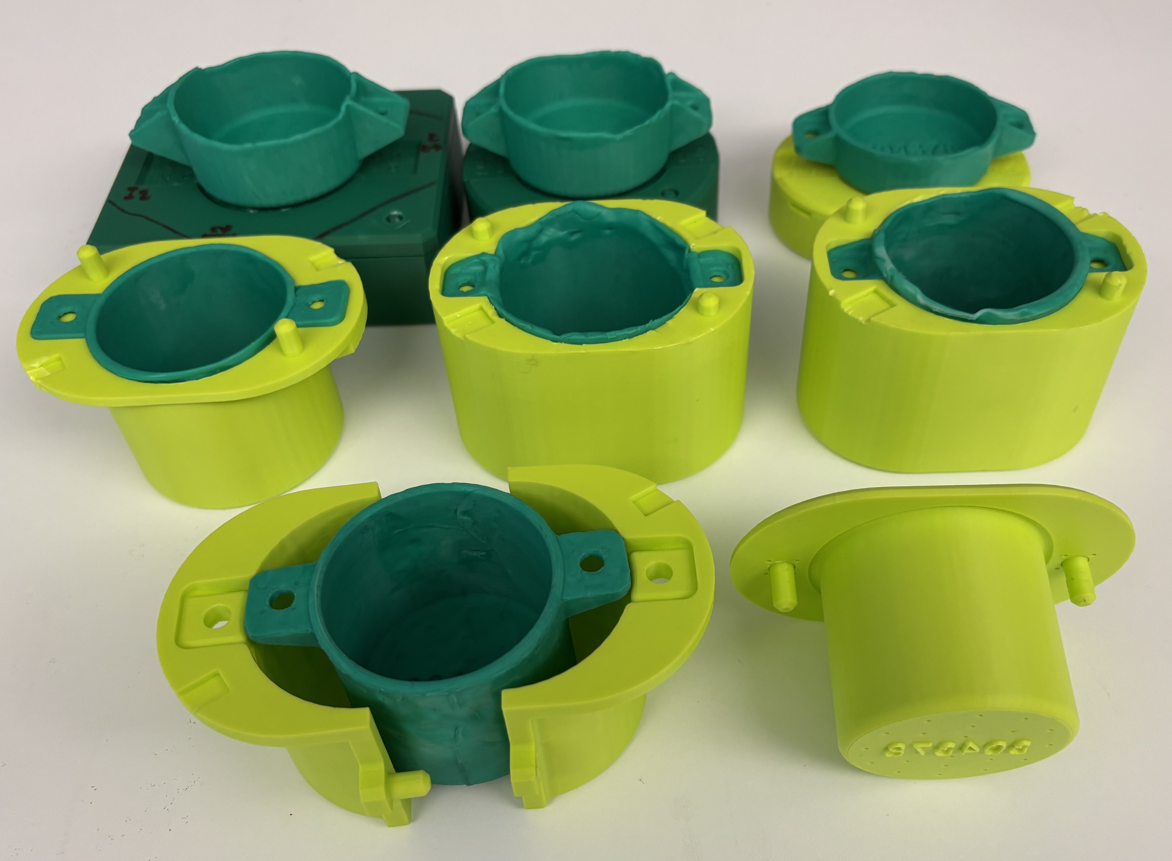
Prototyping
To evaluate fit, tolerances, and removability, I prototyped multiple lens cap designs using two-part silicone in 3D-printed molds. This approach enabled rapid iteration while closely replicating the material behavior of the final parts. I varied wall thickness, clearance, and draft direction to tune the friction fit.
Design Comparison
I prototyped and evaluated horizontal, bottom, and vertical pull-tab removal mechanisms. I compared each option based on ergonomics, material usage, packaging height constraints, and manufacturability.
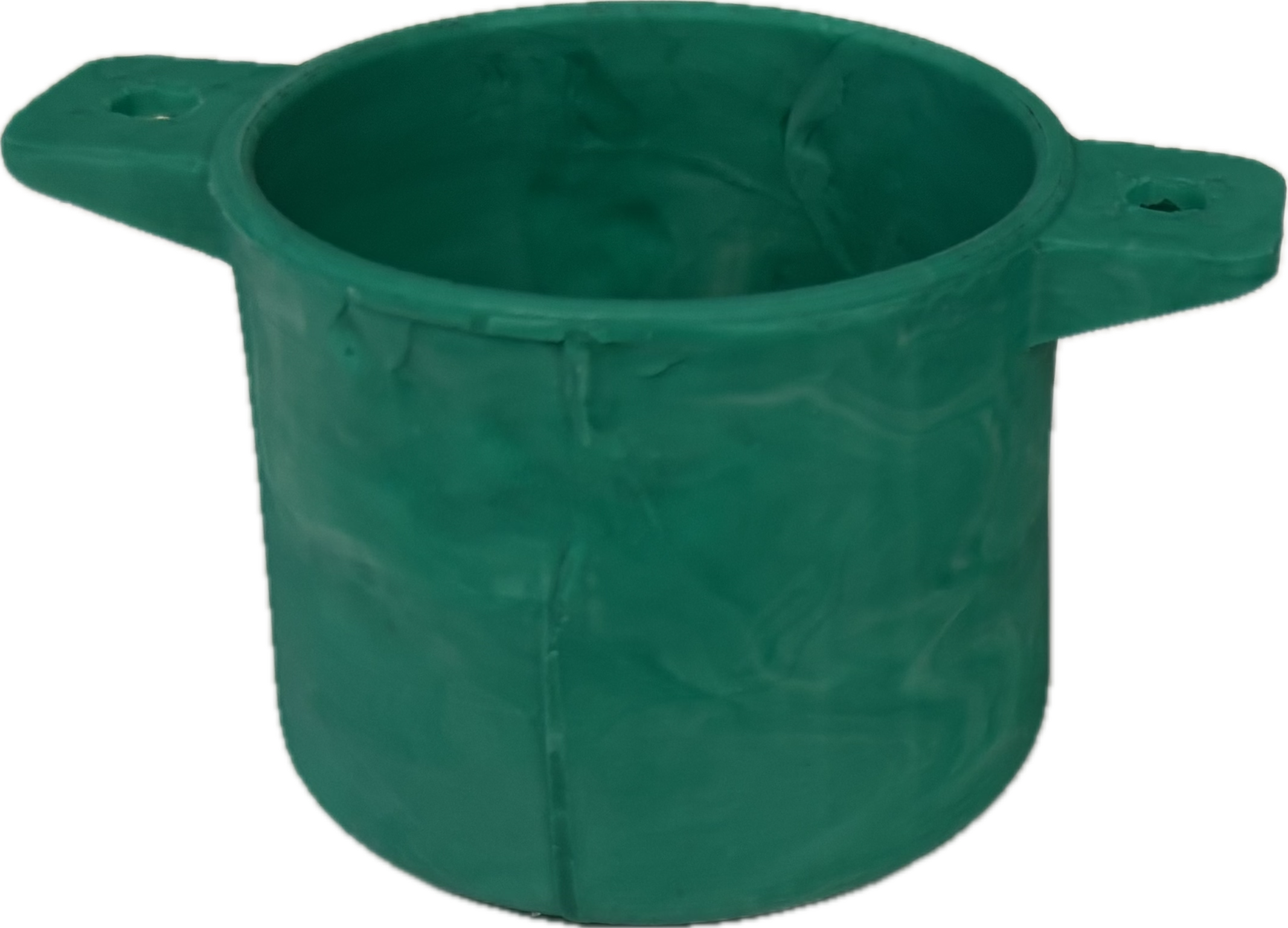
Horizontal Pull Tabs |
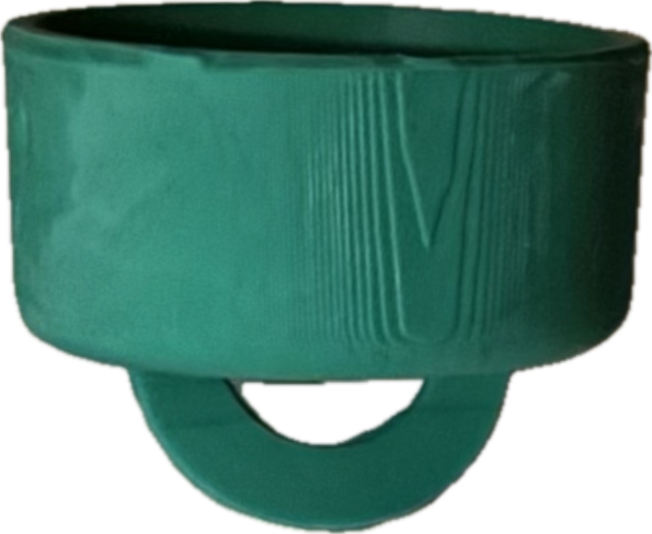
Bottom Pull Tabs |
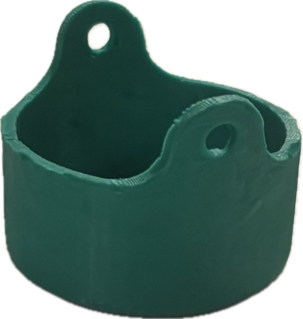
Vertical Pull Tabs |
|---|---|---|
 |
 |
 |
Wall height: 5 cm |
Wall height: 3 cm |
Wall height: 3 cm |
Packaging compliant |
Not Packaging compliant |
Packaging compliant |
Easy grip tabs |
Easy grip tabs |
Harder grip tabs |
Final Design
While the horizontal pull tab was easy to grip, it needed taller walls to extend above the packaging, increasing material use. The bottom pull tab was easy to remove and used less material, but it required modifications to the existing packaging. The vertical pull tab provided the best overall balance, stayed within the packaging envelope, and minimized material while avoiding packaging changes.
Manufacturing Comparison
Given a production volume of 25 parts, I compared several manufacturing methods to balance cost, material properties, and tooling requirements.
3D-printingSilicone |
Injection MoldingAluminum mold |
Silicone Casting3D-printed mold |
|
|---|---|---|---|
Ideal batch size |
1-5 |
1000+ |
25 |
Upfront cost |
Low |
$20,000 |
$1,000 |
Per-part cost |
$12,000 |
$15 |
$50 |
Cost: 25 parts |
$300,000 |
$20,375 |
$2,250 |
Final Manufacturing Method
Injection molding became cost-effective only at much higher production volumes, while 3D-printed elastomers were not cost-efficient. I chose silicone casting to produce these parts because it came at a low tooling cost at the target batch size, making it the most suitable option for small-scale production.