Summary
I designed a camera mounting bracket that provides both structural support and passive heat dissipation for an industrial vision system. The bracket needed to hold the camera rigidly while keeping junction temperature below thermal limits in elevated ambient conditions.
I initially focused on structural stiffness, and the first design significantly exceeded strength and vibration requirements but failed thermal limits during testing. I revised the design to function as an integrated heat sink and validated the final bracket through structural FEA, thermal modeling, simulation, and physical testing, confirming that it met both mechanical and thermal requirements.
Key Features
Dual-function camera bracket for structural support and passive cooling Machined aluminum design with fins to increase surface area for heat transfer Thermal and structural performance validated via simulation and physical testing
Structural
- Bracket must withstand loads from mounted cameras
- Surrounding vibrations must not resonate with the bracket
- Existing camera and yoke mounts must fit the bracket
Thermal
- Bracket must passively cool the heat from the bottom camera
- Junction temperature must not exceed 60 °C
- Bracket must operate from 0-40 °C (tested to 45 °C)
Concept design
I started the design by prioritizing structural stiffness and camera alignment under load. The initial concept used triangular bracing between the camera mounts and the yoke mounting bar, along with a vertical brace connecting the yoke to the base of the bracket. This layout handled the expected camera loads while maintaining compatibility with the existing camera mounts and yoke system.
Structural Analysis
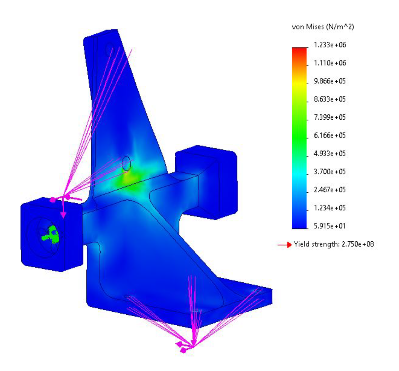
Static FEA
I evaluated bracket strength under translational loads from the mounted cameras to verify stresses remained well below yield. The analysis showed maximum stress far below the material limit, confirming the bracket significantly exceeded strength requirements.
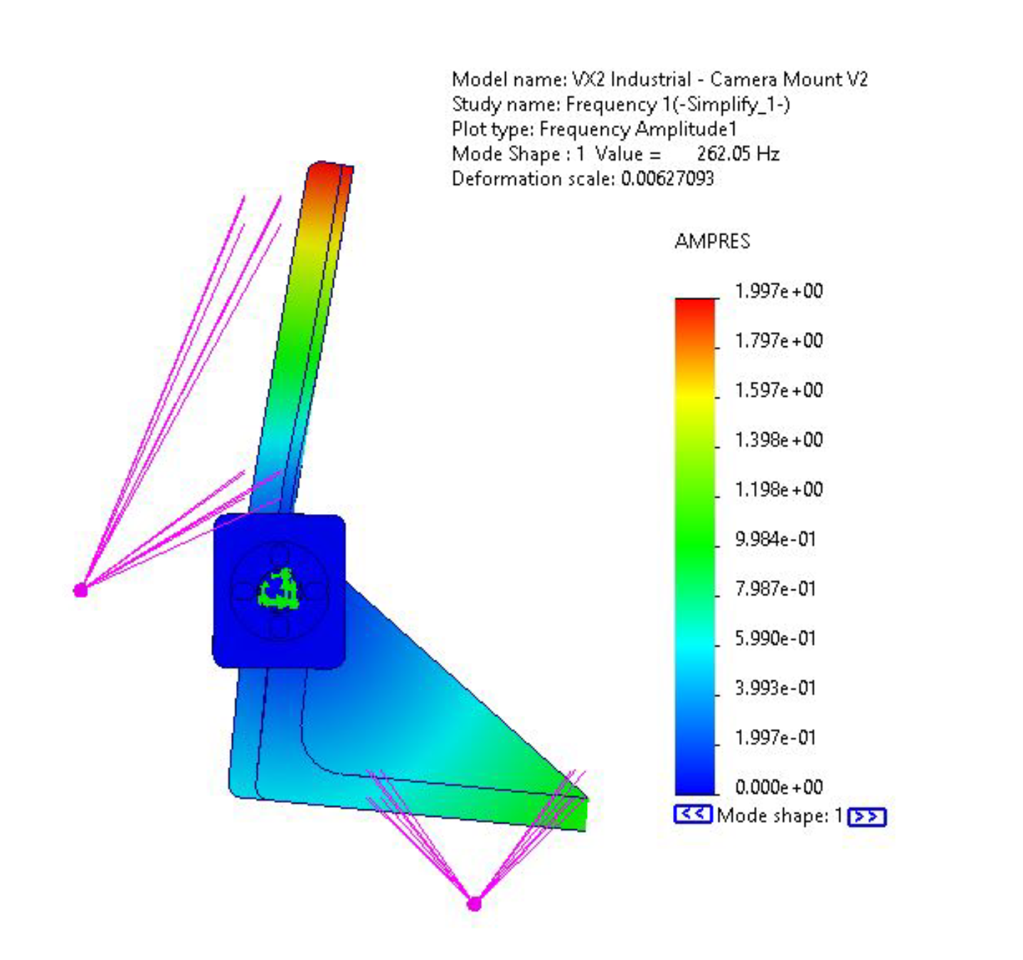
Frequency FEA
I evaluated the bracket's natural frequencies to check for resonance with surrounding vibrations. The lowest mode was well above the 100 Hz target, confirming the bracket would not resonate in the expected operating environment.
Structural Performance
Both static and frequency analyses showed that the initial bracket design exceeded structural requirements by a wide margin. The bracket was significantly overdesigned in terms of strength and stiffness, with large safety margins relative to both yield and vibration targets
Empirical Thermal Testing
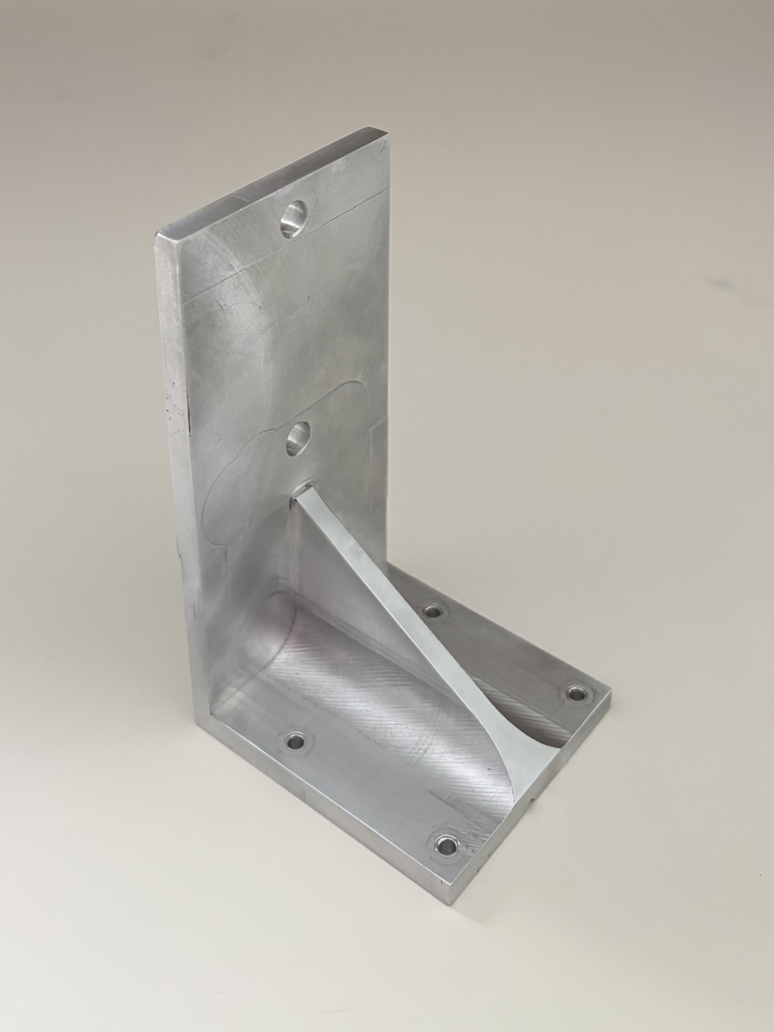
I machined a simplified aluminum bracket and evaluated its thermal performance with the camera powered on. I measured junction temperature over time in open air to determine the system's thermal time constant. Because steady-state testing at elevated ambient conditions risked overheating the system, I tested performance up to a safe temperature limit and used the thermal time constant to estimate steady-state behavior.
The estimated steady-state junction temperature at 45 °C ambient was approximately 61.1 °C, exceeding the 60 °C limit. Based on this result, I redesigned the bracket to improve passive heat dissipation rather than additional structural stiffness.
Test Setup
Machined Part
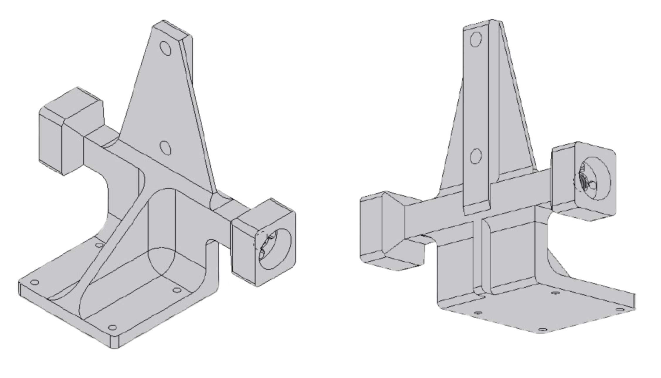
Design Revision: Heat Sink
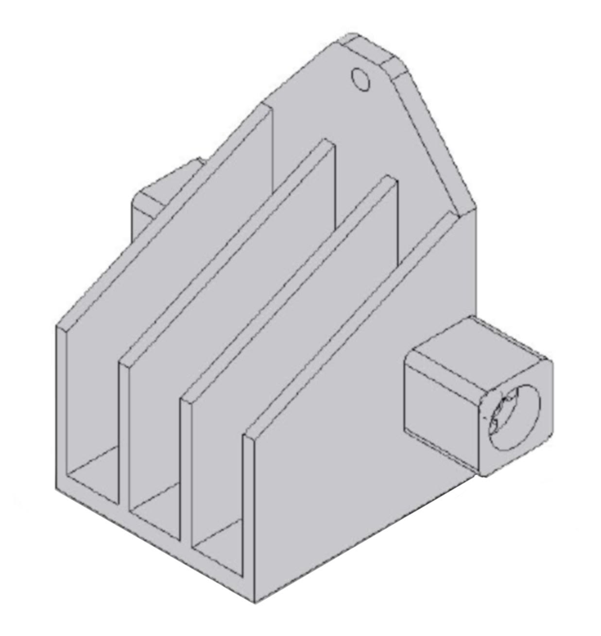
Based on these results, I revised the bracket to act as an integrated heat sink while preserving structural stiffness and mounting compatibility. I increased the base thickness to improve thermal conduction and added four fins to expand surface area for natural convection.
Static FEA
Frequency FEA
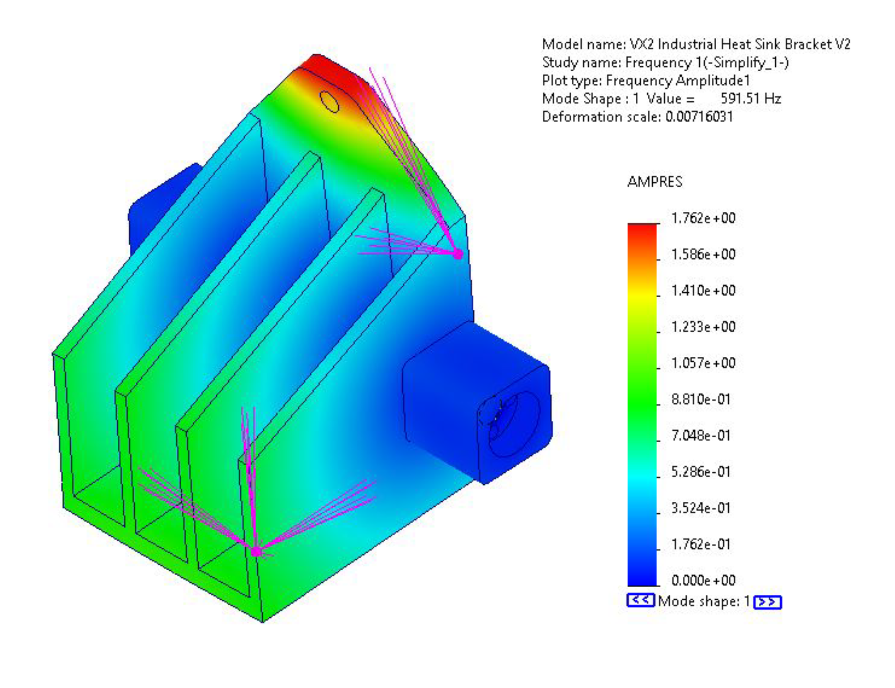
I re-ran static and frequency analyses on the revised heat sink design to confirm that the added material and fins did not compromise structural performance. The updated bracket continued to exceed strength requirements by a wide margin, and the lowest natural frequency remained well above the vibration threshold. These results confirmed that the thermal redesign preserved the original structural performance.
Theoretical Thermal Model
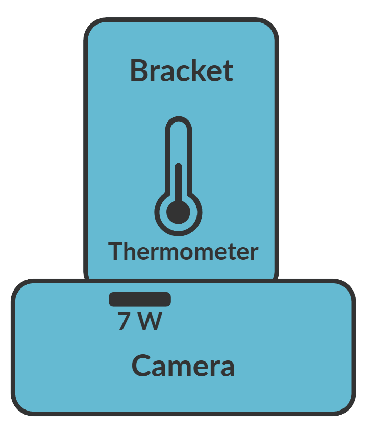
I developed a thermal-resistance model to estimate the revised bracket's steady-state junction temperature, assuming a 7 W heat load dissipated at the back of the camera. I modeled the system as interface, spreading, and convective thermal resistances between the camera and ambient air.
Using the bracket geometry and an assumed skin temperature, I calculated total thermal resistance and estimated junction temperature under worst-case ambient conditions. Because convective resistance depends on skin temperature, I solved the model iteratively to converge on a steady-state solution.
The revised heat sink design reduced total thermal resistance and lowered the predicted junction temperature to approximately 58.4 °C, within the allowable limit. Applying the same model to the original concept predicted a junction temperature of approximately 62.1 °C, within 1 °C of the empirical result.
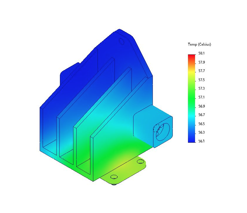
Thermal FEA
I performed a thermal FEA in SolidWorks to validate the revised heat sink design under worst-case ambient conditions. I applied heat generation at the camera mounting interface and modeled natural convection on all exposed bracket surfaces. The analysis showed the surface temperature reached 58.4 °C, further confirming the redesign dissipates the camera heat effectively.
Results
The redesigned bracket with an integrated heat sink successfully reduced junction temperature while maintaining the required structural stiffness and vibration performance. Analytical modeling, thermal FEA, and empirical testing confirmed that the design kept the camera junction temperature below 60 °C under worst-case ambient conditions.